How Transparent Displays Put Information on Glass
Head-up displays, smart glasses and illuminated sights all solve one problem: adding light to a view without blocking it. Here is how beam splitters, curved combiners and waveguides do it, and what each one gives up.
How Optics Work, Part 4. Earlier in the series: Part 1: How a Holographic Sight Actually Works, Part 2: Why the Reticle Looks Far Away and Part 3: Parallax Explained.
Every see-through display has the same job. It has to add light from a display to the light coming from the world, in the same direction, without blocking the world. An aircraft head-up display (HUD), a pair of smart glasses and the reflex sights from Part 1 all solve this problem. The optical element that merges the two paths is called a combiner. There are only a handful of ways to build one, and each makes a different compromise.
The basic recipe
A see-through display needs three things. It needs a light source that carries the image, such as an LED, a microdisplay or a laser. It needs optics that collimate that light so the image appears far away (the subject of Part 2). And it needs a combiner, which sends that light to the eye while letting the world's light through. Wikipedia describes a typical aircraft HUD as "a projector unit, a combiner, and a video generation computer" (Wikipedia: Head-up display).
The combiner is where most of the compromises live. In their review of waveguide combiners, Kress and Chatterjee call it "the one component seen directly by the user and the one seen directly by the world" (Kress and Chatterjee, Nanophotonics, 2021).
The flat beam splitter
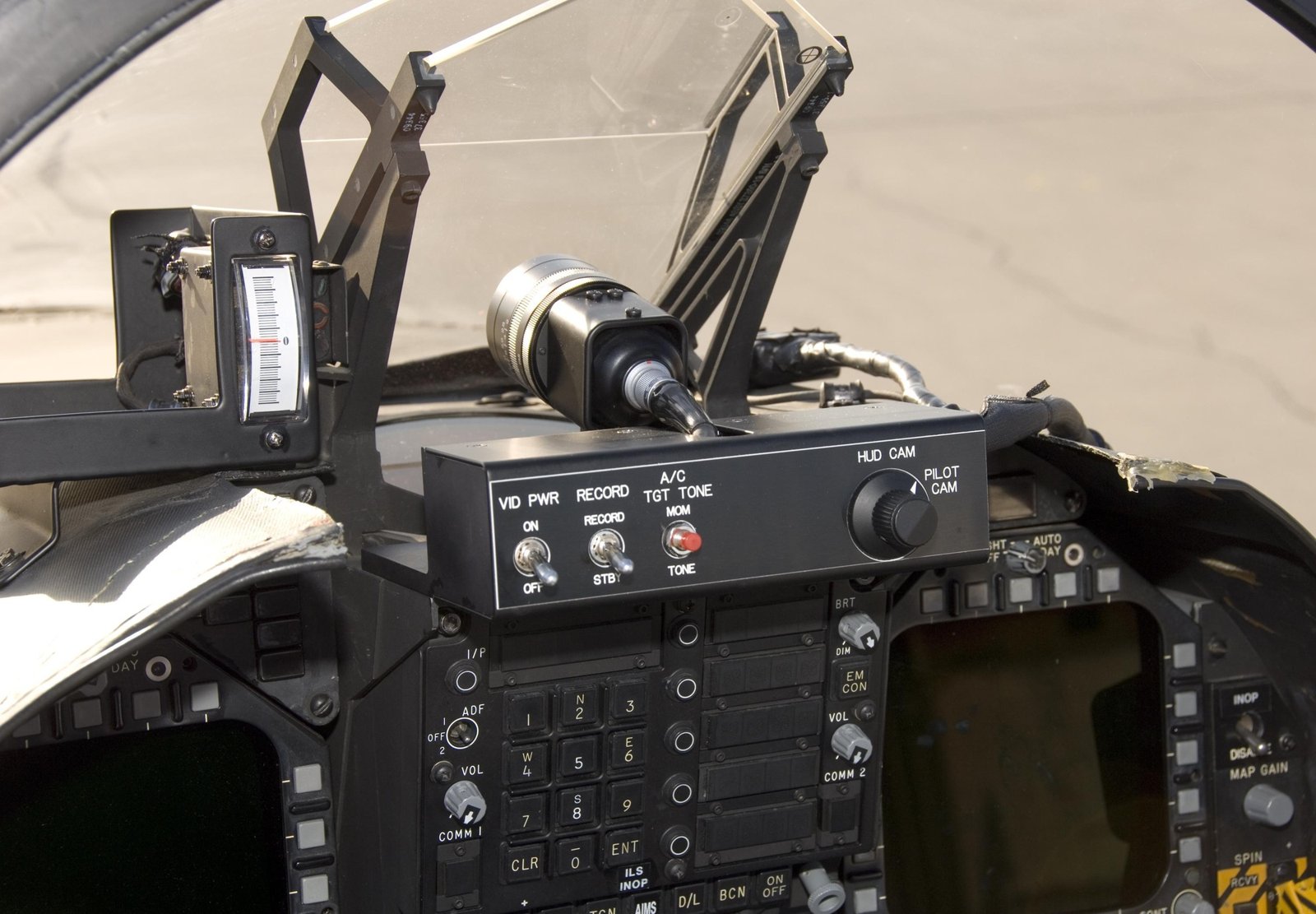
The simplest combiner is a flat, partially reflecting plate tilted in front of the eye. Collimated light from the display reflects off it toward the eye, and light from the world passes through it. A plate beamsplitter is a thin glass plate with a coating on its first surface. Edmund Optics notes that most have an anti-reflection coating on the second surface "to remove unwanted Fresnel reflections", which would otherwise make a faint second image (Edmund Optics: What are beamsplitters?). Wikipedia describes the classic HUD combiner as "an angled flat piece of glass (a beam splitter)" (Wikipedia: Head-up display).

Try itRaise the reflectance and watch the world darken. Then switch to the selective coating.
Figure 1. A flat combiner. The plate reflects a fraction R of the display light toward the eye and transmits a fraction T of the world's light. If absorption is ignored, R + T = 1, so the brighter you make the overlay this way, the darker the world looks. Schematic, not to scale.
This exposes the central trade-off. A plate's coating has some reflectance R and some transmittance T. If absorption is small, the two add up to roughly one. Raise R to make the overlay brighter, and the world behind it gets dimmer. Lower R to keep the world bright, and you need a brighter display to compensate.
Making the combiner selective
There is a way round part of that trade-off. If the display emits a narrow band of colour, the combiner coating can reflect strongly in that band and weakly everywhere else. Wikipedia notes that HUD combiners often have "special coatings that reflect the monochromatic light projected onto it from the projector unit while allowing all other wavelengths of light to pass through" (Wikipedia: Head-up display). Red dot sights use the same idea, with a dichroic coating tuned to the LED's red (Wikipedia: Red dot sight; Wikipedia: Dichroic filter).
A selective coating can reflect a large share of the display's light while still passing most of the world's light. The cost is that the world loses some light in that band, which can show as a slight tint.
The curved combiner
A flat combiner needs separate collimating optics, usually a lens between the display and the plate. A curved combiner can do both jobs at once. If the partially reflecting surface is itself a concave mirror with the source at its focal point, the reflection comes back collimated. This is the arrangement in a reflex sight, and some HUDs use it too. Wikipedia notes that "in some optical layouts combiners may also have a curved surface to refocus the image from the projector" (Wikipedia: Reflector sight; Wikipedia: Head-up display).

Try itSwitch to a spherical mirror and widen the window. The edge rays tilt away from parallel.
Figure 2. A curved combiner collimates and combines in one surface. The source sits off-axis so it does not block the view. Off-axis use brings aberrations that the designer has to control. Schematic, not to scale. The interactive traces real reflections from a mirror used much further off-axis than in a real sight, so the angles are exaggerated.
Folding the collimator into the combiner saves parts and space. The price is that an off-axis curved mirror introduces aberrations, the same imperfections behind the edge-of-window effects discussed in Part 3. For a single dot, these are manageable. For a large, detailed image they become harder to correct.
The waveguide
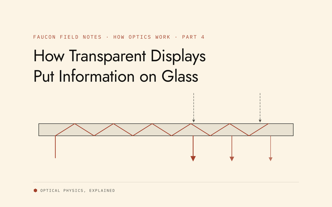
The third approach carries the light inside the glass. A waveguide combiner is a thin, flat plate of glass or plastic. Display light is coupled into one end, travels along the plate by total internal reflection, and is coupled out in front of the eye (Wikipedia: Waveguide (optics); OpenStax: Total Internal Reflection).
Total internal reflection happens when light inside a denser material meets its surface at more than the critical angle. All of it then reflects. For glass with a refractive index of 1.5, the critical angle is about 41.8°. For a high-index glass near 1.8, it is around 34° (OpenStax: Total Internal Reflection; Zhang et al., Scientific Reports, 2024). A lower critical angle means a wider range of ray angles can be trapped and carried. That is one reason higher-index materials are linked to wider fields of view in waveguide displays (Kress and Chatterjee, 2021).

Try itLower the ray angle below the critical angle and the light escapes. Raise the index to trap it again.
Figure 3. A waveguide combiner. An in-coupler (a grating, prism or mirror) traps the light. Total internal reflection carries it along the plate. An out-coupler releases part of it at each bounce, copying the exit pupil across a wider area. Schematic, not to scale.
The in-coupler and out-coupler can be prisms, embedded partial mirrors, surface-relief gratings, holographic gratings or other structures (Kress and Chatterjee, 2021). The out-coupler releases only part of the light at each bounce. The rest carries on to the next bounce, where more is released. This copies the image's exit pupil several times across the plate, an approach called exit pupil expansion. Kress and Chatterjee describe waveguide combiners as "essentially acting as a transparent periscope with a single entrance pupil and often many exit pupils" (Kress and Chatterjee, 2021).
Wikipedia's history of HUDs lists waveguides as the third generation of the technology. These systems "produce images directly in the combiner rather than use a projection system" (Wikipedia: Head-up display).
The trade-offs
Four quantities pull against each other in every combiner design.
- Brightness. How much display light reaches the eye. This is limited by the combiner's reflectance or, in a waveguide, by coupling efficiency and by how widely the light is spread.
- Transparency. How much world light gets through, and how evenly across colours.
- Field of view. The angular size of the overlay. A narrow field of view limits how much of the scene can carry information.
- Eyebox. The volume in which the eye can sit and still see the whole image. Wikipedia describes the HUD eyebox as the region inside the "cylinder of parallel light" that the collimator produces, and gives modern HUD eyeboxes as roughly 5 by 3 by 6 inches (Wikipedia: Head-up display; Wikipedia: Exit pupil).
| Combiner type | What it does well | What it gives up |
|---|---|---|
| Flat beam splitter | Simple, good image quality, easy to make | Needs separate collimating optics; overlay brightness trades directly against see-through brightness |
| Curved combiner | Collimates and combines in one surface; compact | Off-axis aberrations grow with image size; the curved surface must be very precise |
| Waveguide | Thin, flat form; pupil expansion gives a large eyebox from small optics | Light spread across many exit pupils; field of view limited by index and coupler design; colour uniformity is harder |
A general summary of the trade-offs in the sources cited. Specific products vary widely.
The eyebox and field of view are linked. Optics conserve a quantity called étendue, roughly the product of a beam's area and its spread of angles. A small display can only produce so much of it (Wikipedia: Etendue). Spreading the image across a larger eyebox, or a wider field of view, means the same light covers more area or angle. Kress and Chatterjee identify the combiner as the element that "defines the EB [eyebox] size (and in many cases, also the FOV)" (Kress and Chatterjee, 2021).
The upshot is that no combiner is best on every axis. Each architecture moves the compromise rather than removing it, which is why HUDs, smart glasses and sights use different designs for different jobs.
Key points
- A combiner merges display light and world light into the same view, usually with collimated display light.
- A flat beam splitter trades overlay brightness directly against see-through brightness, unless its coating is wavelength-selective.
- A curved combiner collimates as well as combines, at the cost of off-axis aberrations.
- A waveguide carries light by total internal reflection and copies the exit pupil to enlarge the eyebox. Its field of view depends on refractive index and coupler design.
- Brightness, transparency, field of view and eyebox trade against each other in every design.
Sources
Every source below was opened and checked on 6 November 2026, except where noted. The critical angle for n = 1.5 is our own calculation from the formula in the OpenStax source.
- Wikipedia, "Head-up display": https://en.wikipedia.org/wiki/Head-up_display
- Kress, B. C. and Chatterjee, I., "Waveguide combiners for mixed reality headsets: a nanophotonics design perspective," Nanophotonics 10(1), 41–74 (2021), open access: https://doi.org/10.1515/nanoph-2020-0410 (the publisher's site blocks automated checks, so we confirmed the quoted text through a search index rather than a direct page load)
- Edmund Optics, "What are beamsplitters?": https://www.edmundoptics.com/knowledge-center/application-notes/optics/what-are-beamsplitters/
- Wikipedia, "Red dot sight": https://en.wikipedia.org/wiki/Red_dot_sight
- Wikipedia, "Dichroic filter": https://en.wikipedia.org/wiki/Dichroic_filter
- Wikipedia, "Reflector sight": https://en.wikipedia.org/wiki/Reflector_sight
- Wikipedia, "Waveguide (optics)": https://en.wikipedia.org/wiki/Waveguide_(optics)
- OpenStax, University Physics Volume 3, 1.4 "Total Internal Reflection": https://openstax.org/books/university-physics-volume-3/pages/1-4-total-internal-reflection
- Zhang et al., "Design of waveguide with double layer diffractive optical elements for augmented reality displays," Scientific Reports (2024): https://doi.org/10.1038/s41598-024-75766-7
- Wikipedia, "Exit pupil": https://en.wikipedia.org/wiki/Exit_pupil
- Wikipedia, "Etendue": https://en.wikipedia.org/wiki/Etendue
- DVIDS, image 757438 (NASA photo, public domain): https://www.dvidshub.net/image/757438